Remote Medical Evacuation Pod
This project involved the design of a remote medical evacuation pod for patient extraction in wildfire environments where road-based evacuation may be limited. The pod was developed as a lightweight, manually carried system intended to protect a patient from heat, smoke, ash, and unstable terrain during transport to a helicopter extraction point.
The final concept combines an aluminium internal frame, an insulated fibreglass enclosure, a filtered ventilation system, adjustable patient support, and ergonomic handling points for four rescuers. The work shown here summarises the main engineering decisions, design features, CAD work, and verification outcomes from the full group design project.
This project was completed by a four-member engineering design team. The work presented on this page reflects the collective project outcome and is included for portfolio purposes.
Project Overview
Existing evacuation equipment does not fully address the combined requirements of wildfire rescue: heat protection, smoke and ash protection, low weight, manual transportation, patient restraint, and helicopter compatibility. The design brief required a pod capable of carrying a patient of up to 90 kg, while keeping the pod mass below 40 kg and allowing four rescuers to manually transport the system over approximately 500 m.
Requirements
My Contributions
- CAD modelling and assembly development
- Concept development and comparison
- Material selection for key subsystems
- Structural design verification and calculations
- Engineering drawings and visual documentation
- Subsystem description and final design communication
Final Design
The selected concept uses a hybrid structure consisting of a lightweight aluminium internal frame enclosed by an insulated fibreglass shell. The internal frame carries the main structural loads, while the outer enclosure provides environmental protection. This separation improves load transfer, makes the system more maintainable, and reduces the risk of localised failure in the shell.

Figure 1: CAD model of the selected evacuation pod concept, showing the enclosed patient compartment, internal support system, viewing window, and carrying interfaces.
Key Design Features
Concept Development
Three concept directions were developed and compared against safety, weight, ventilation, stiffness, load capacity, thermal performance, and manufacturability. The third concept was selected because it offered the strongest balance between structural reliability and patient protection.
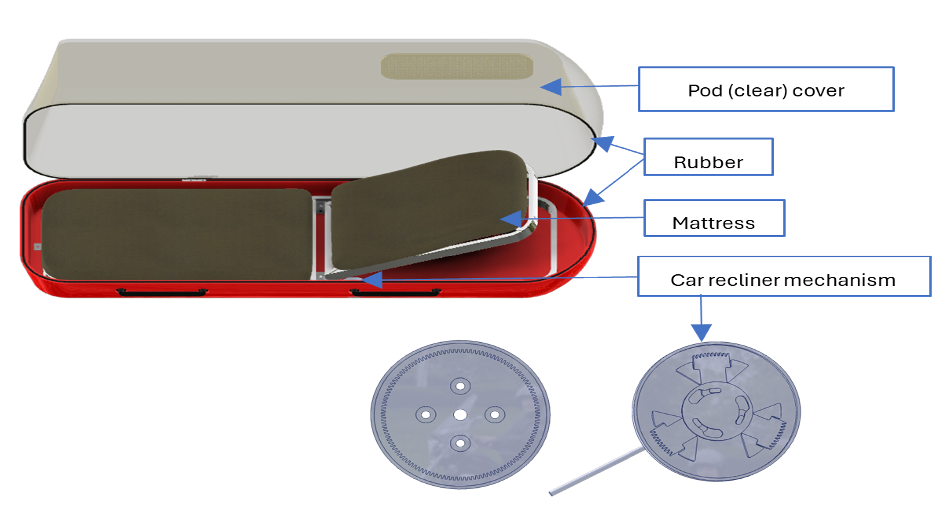
Figure 2: Concept 1 explored a rigid transparent cover, aluminium frame, ventilation mesh, and recliner-based torso adjustment.

Figure 3: Concept 2 explored a cylindrical shell with an integrated access panel, internal supports, and carrying handles.
Figure 4: Concept 3 was selected as the final design due to its internal frame, insulated shell, filtered ventilation, and improved patient support arrangement.
Concept Selection Summary
| Concept | Main Strength | Limitation | Outcome |
|---|---|---|---|
| Concept 1 | Simple enclosure and recliner-based torso adjustment | Lower thermal protection and less efficient load path | Not selected |
| Concept 2 | Efficient cylindrical geometry and reduced internal structure | Less dedicated insulation and lower active ventilation performance | Not selected |
| Concept 3 | Strong internal frame, insulated shell, and improved patient protection | Higher manufacturing complexity | Selected final concept |
Material Selection
Materials were selected to balance strength, weight, thermal protection, durability, and manufacturability. The design uses lightweight structural materials for load-bearing components and insulated composite materials for environmental protection.
| Component | Material | Reason for Selection |
|---|---|---|
| Internal Frame | Aluminium 6061-T6 | High strength-to-weight ratio, good durability, and suitable structural performance. |
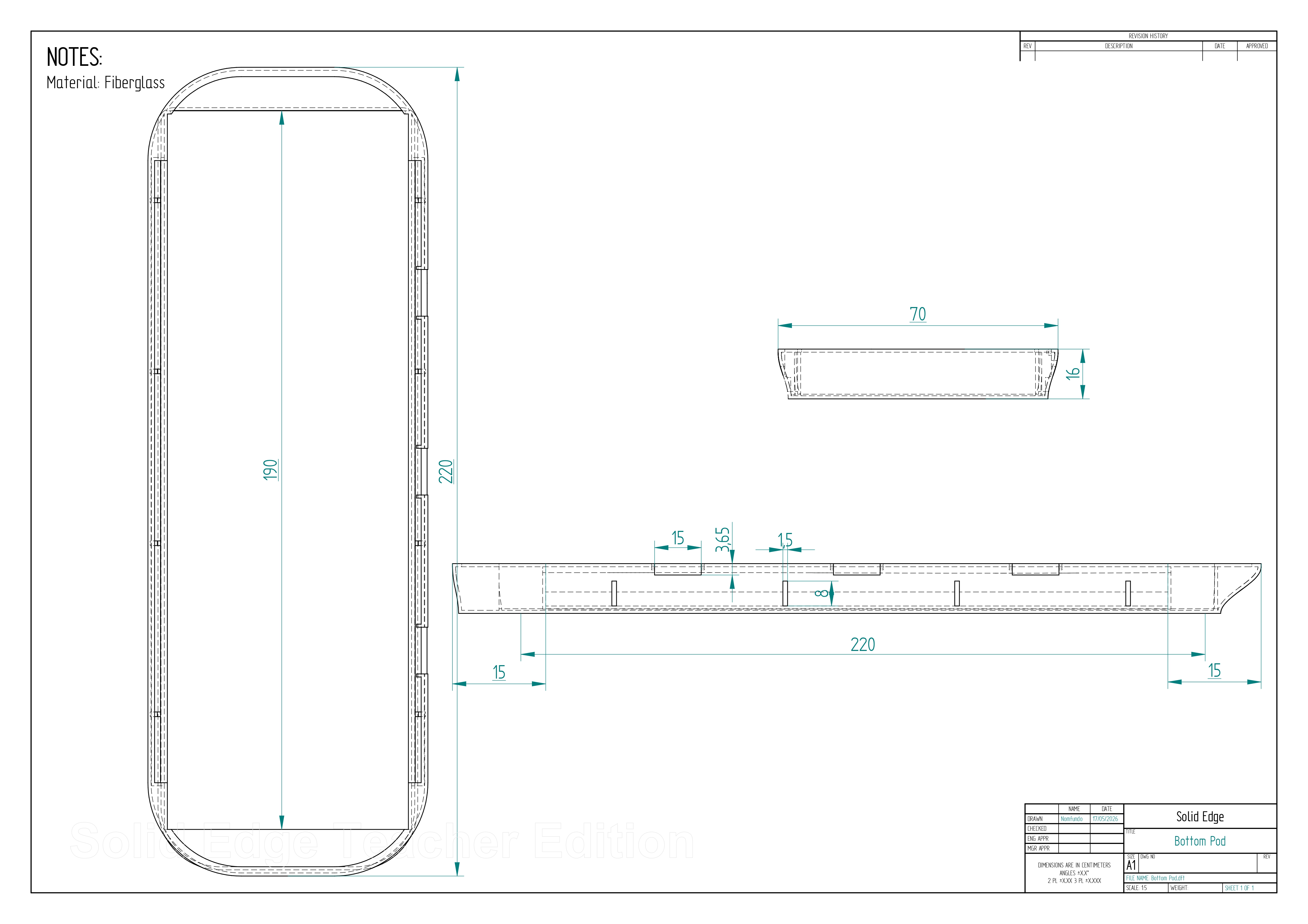
| Outer Shell | Fibreglass Reinforced Polymer with Polyurethane Foam Core | Provides thermal insulation, low mass, impact resistance, and environmental protection. |
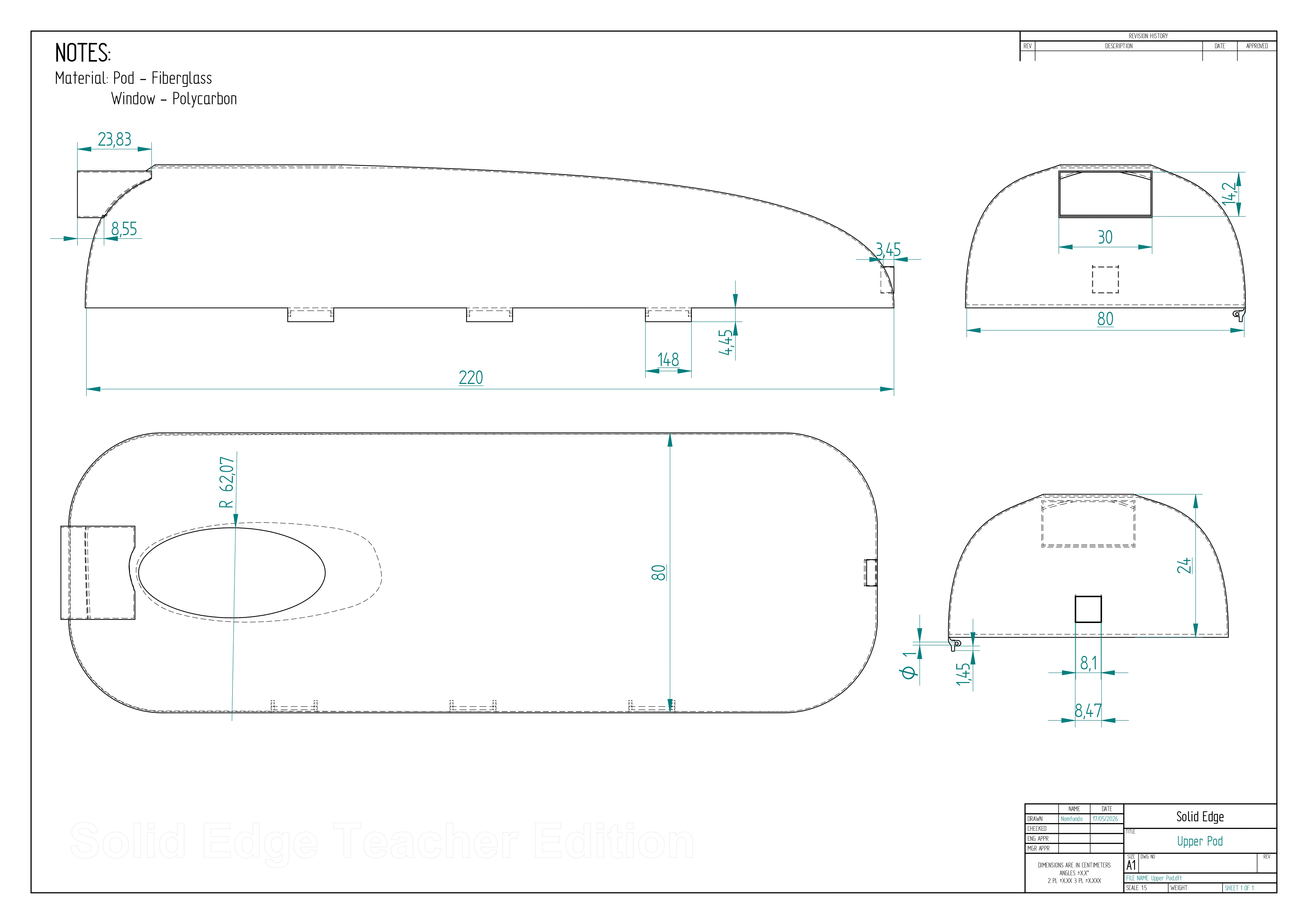
| Viewing Window | Polycarbonate | Transparent, lightweight, and impact resistant for patient monitoring. |
| Patient Support | EVA Closed-Cell Foam | Provides cushioning, vibration absorption, and pressure distribution. |
| Restraining Straps | Nylon Webbing | Strong, adjustable, and suitable for securing the patient during transport. |
| Handles | Aluminium 6061-T6 with Silicone Grip Covers | Lightweight structural handling points with improved grip and heat isolation. |
Engineering Analysis
The structural frame was analysed under worst-case carrying conditions, assuming the pod behaves like a simply supported beam between the handle locations. Dynamic loading and a safety factor were included to account for walking motion, uneven terrain, and emergency handling conditions.
Structural Verification Summary
| Parameter | Value |
|---|---|
| Maximum patient mass | 90 kg |
| Pod mass | 38.6 kg |
| Maximum design load | 3531.6 N |
| Frame material | Aluminium 6061-T6 |
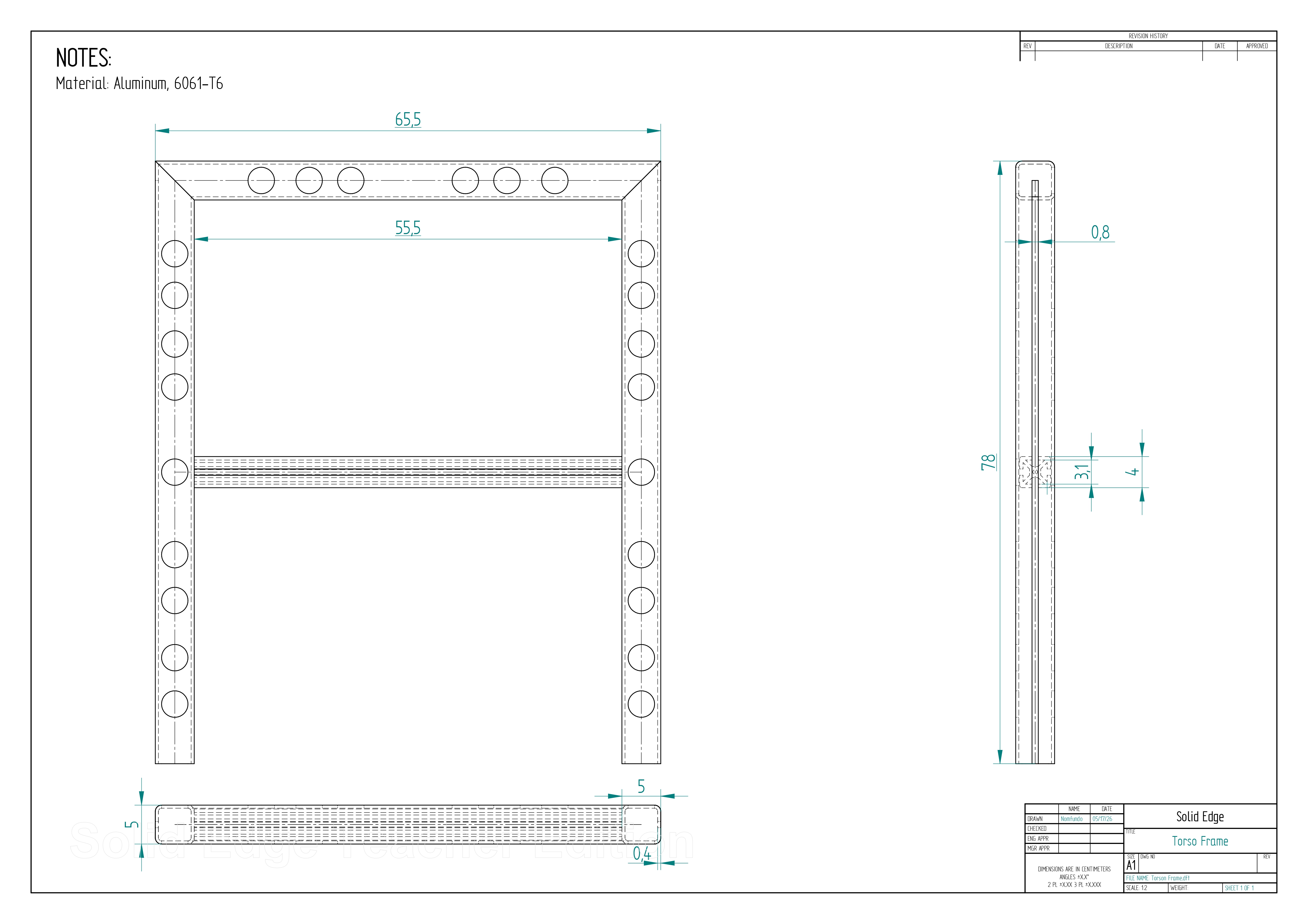
| Frame cross-section | 40 mm × 40 mm hollow square section |
| Maximum frame bending stress | 138 MPa |
| Material yield strength | 240 MPa |
| Approximate factor of safety | ≈ 2 |
The calculated bending stress remained below the yield strength of Aluminium 6061-T6, confirming that the selected frame members satisfy the strength requirements for the design load case considered.
Thermal and Environmental Considerations
The enclosure was designed using fibreglass reinforced polymer with a polyurethane foam core to reduce heat transfer into the pod. Filtered vents and compact fans were included to assist airflow and reduce smoke and ash accumulation inside the patient compartment.
- External design temperature: up to 60°C
- Estimated evacuation distance: 500 m
- Estimated evacuation duration: 9–10 minutes
- Insulation system: FRP shell with polyurethane foam core
- Ventilation: filtered airflow with HEPA protection
Technical Specifications
| Category | Specification | Value |
|---|---|---|
| Performance | Maximum Patient Mass | 90 kg |
| Performance | Pod Mass | 38.6 kg |
| Dimensions | Overall Length | 2200 mm |
| Dimensions | Overall Width | 800 mm |
| Dimensions | Overall Height | 400 mm |
| Patient Support | Backrest Inclination | 0°–20° |
| Structure | Primary Frame Material | Aluminium 6061-T6 |
| Environmental Protection | Shell Material | FRP + Polyurethane Foam Core |
| Ventilation | Filtration | HEPA-filtered airflow |
| Handling | Manual Carrying | Four side handles for four rescuers |
Subsystem CAD Views
The pod was separated into key subsystems to improve clarity during modelling, design verification, and documentation.
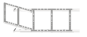
Figure 5: Structural support subsystem showing the aluminium internal frame used to carry patient and handling loads.
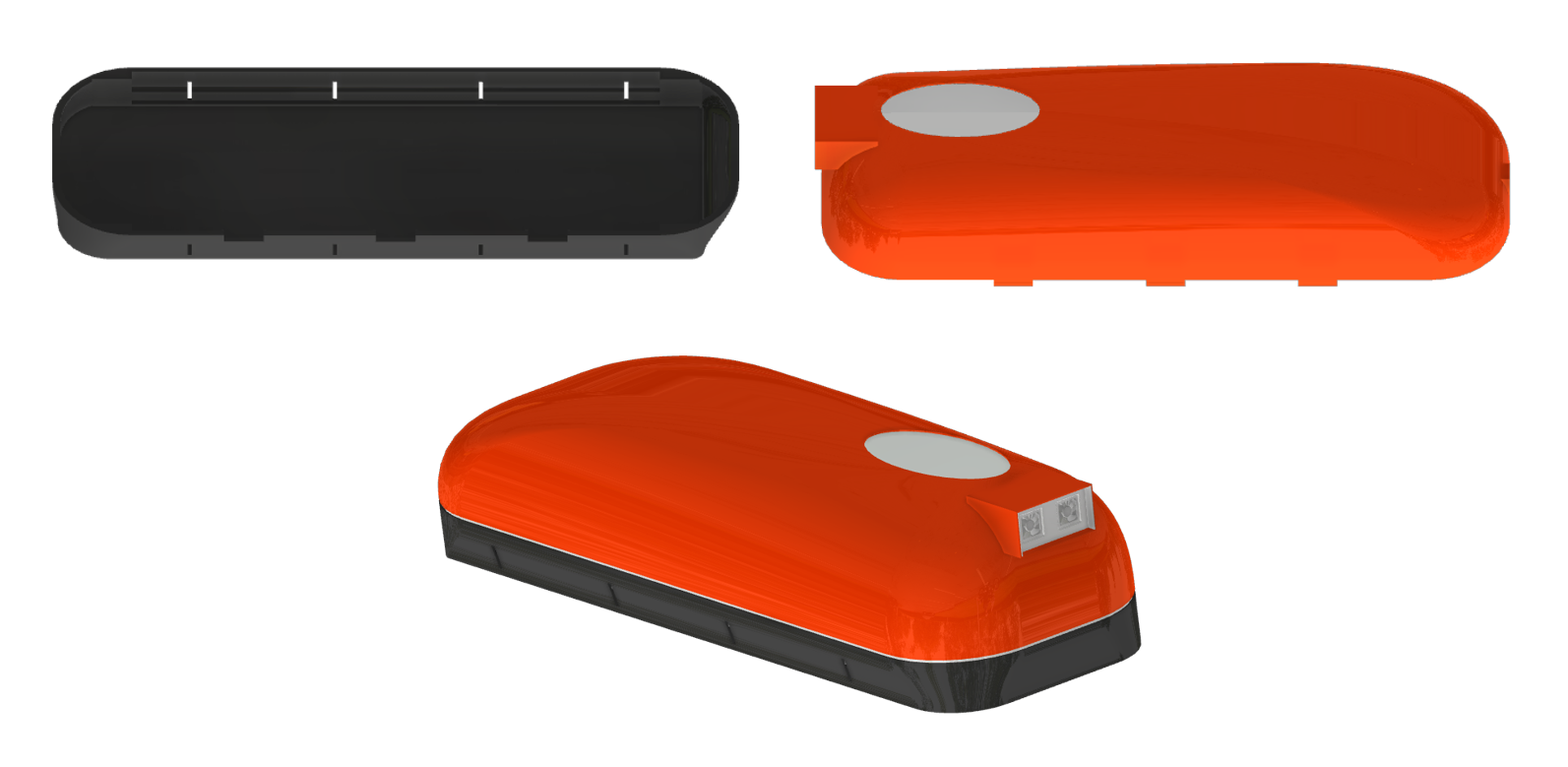
Figure 6: Environmental protection subsystem showing the insulated enclosure and patient monitoring window.
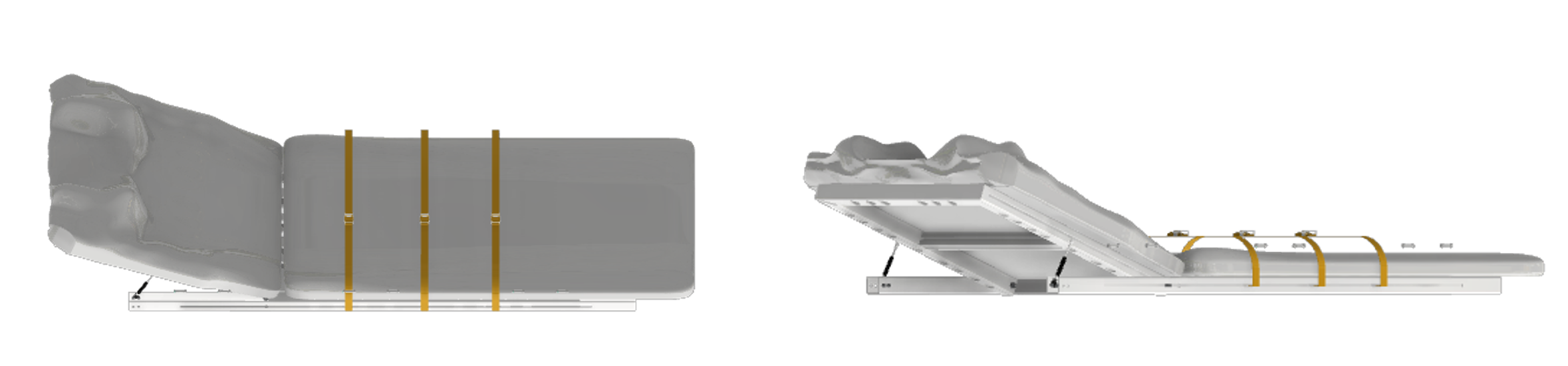
Figure 7: Patient support platform subsystem including cushioning, restraint points, and torso inclination support.

Figure 8: Handling and load interface subsystem showing the external carrying handles and load transfer points.
Engineering Drawings
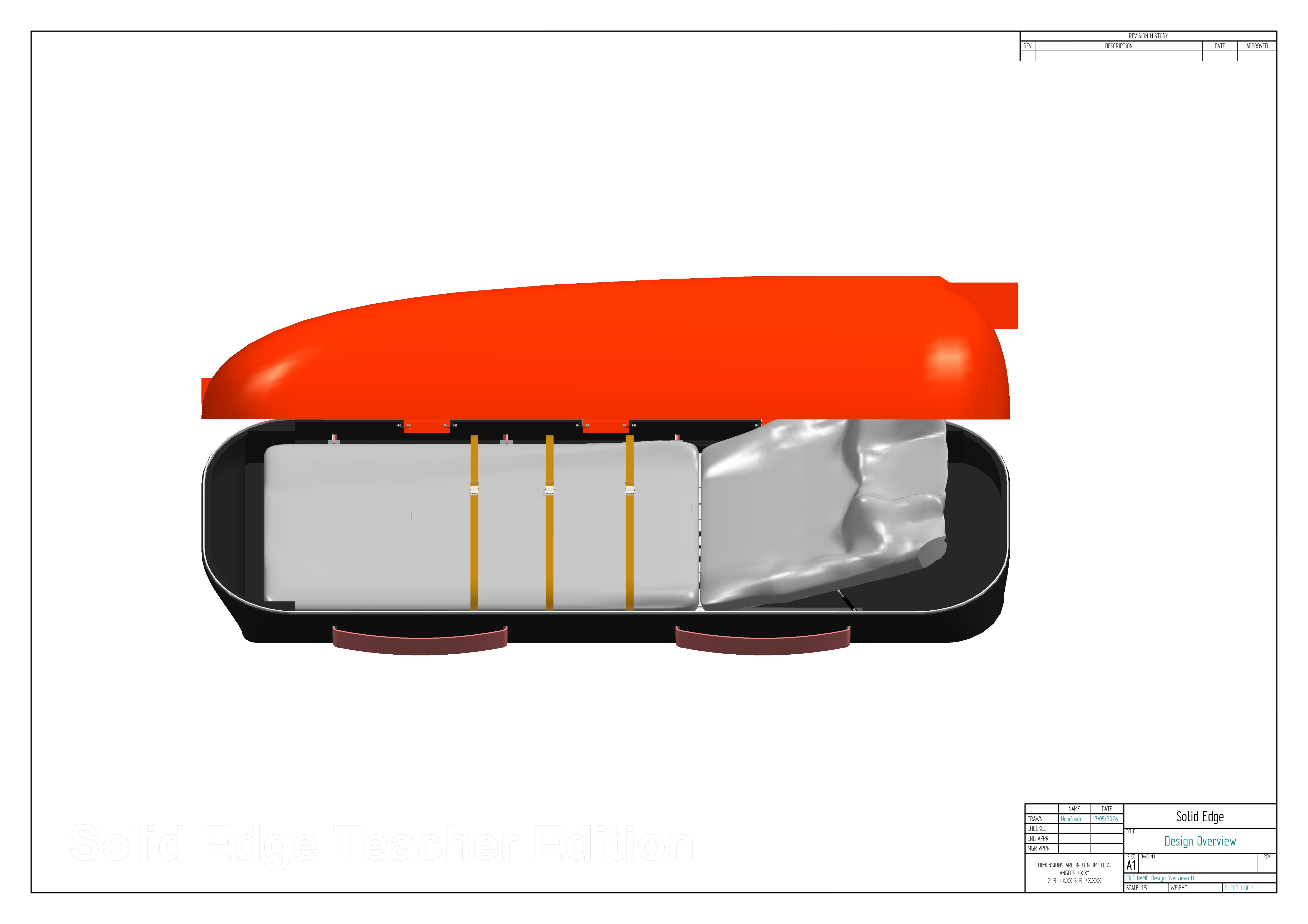
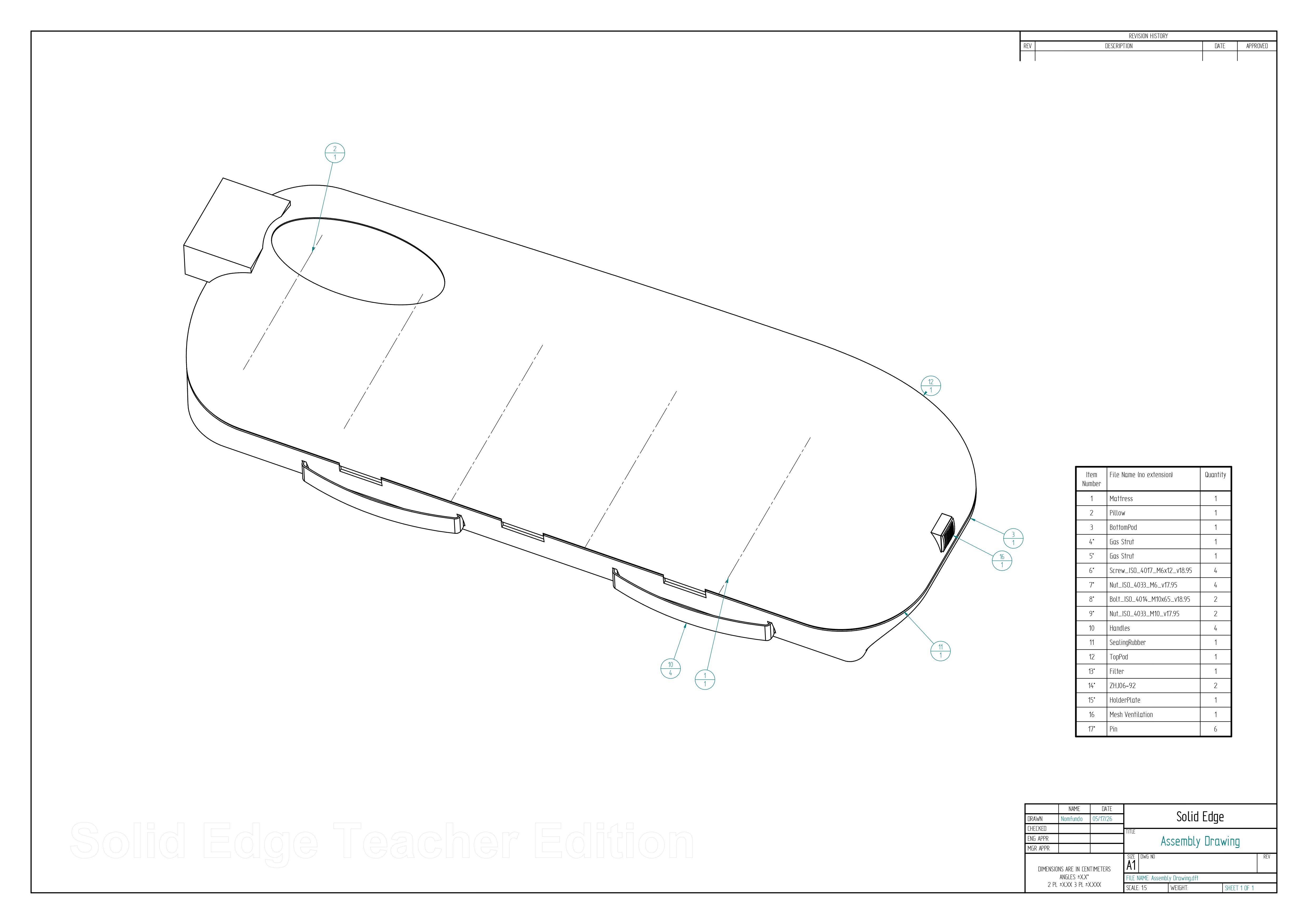
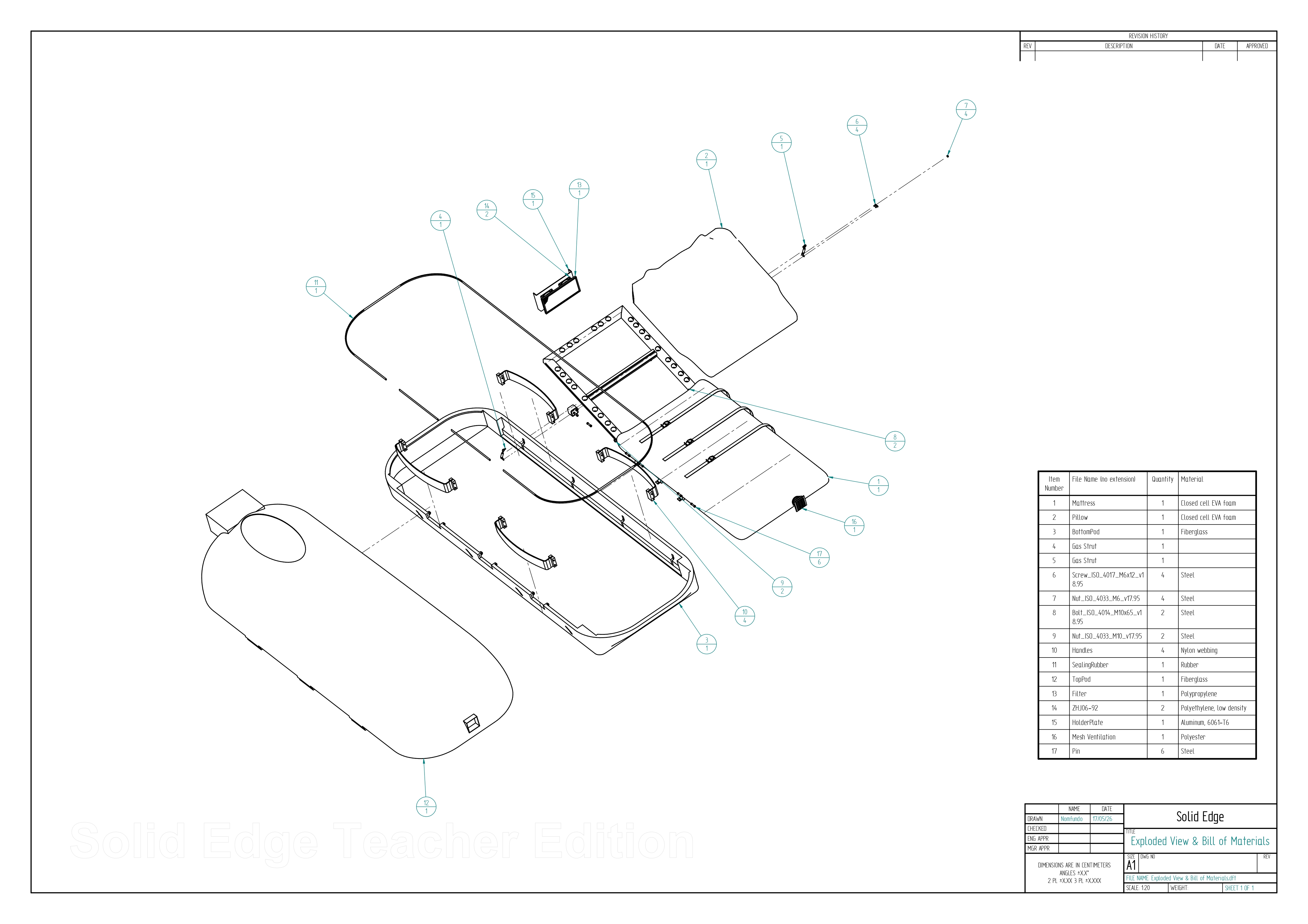
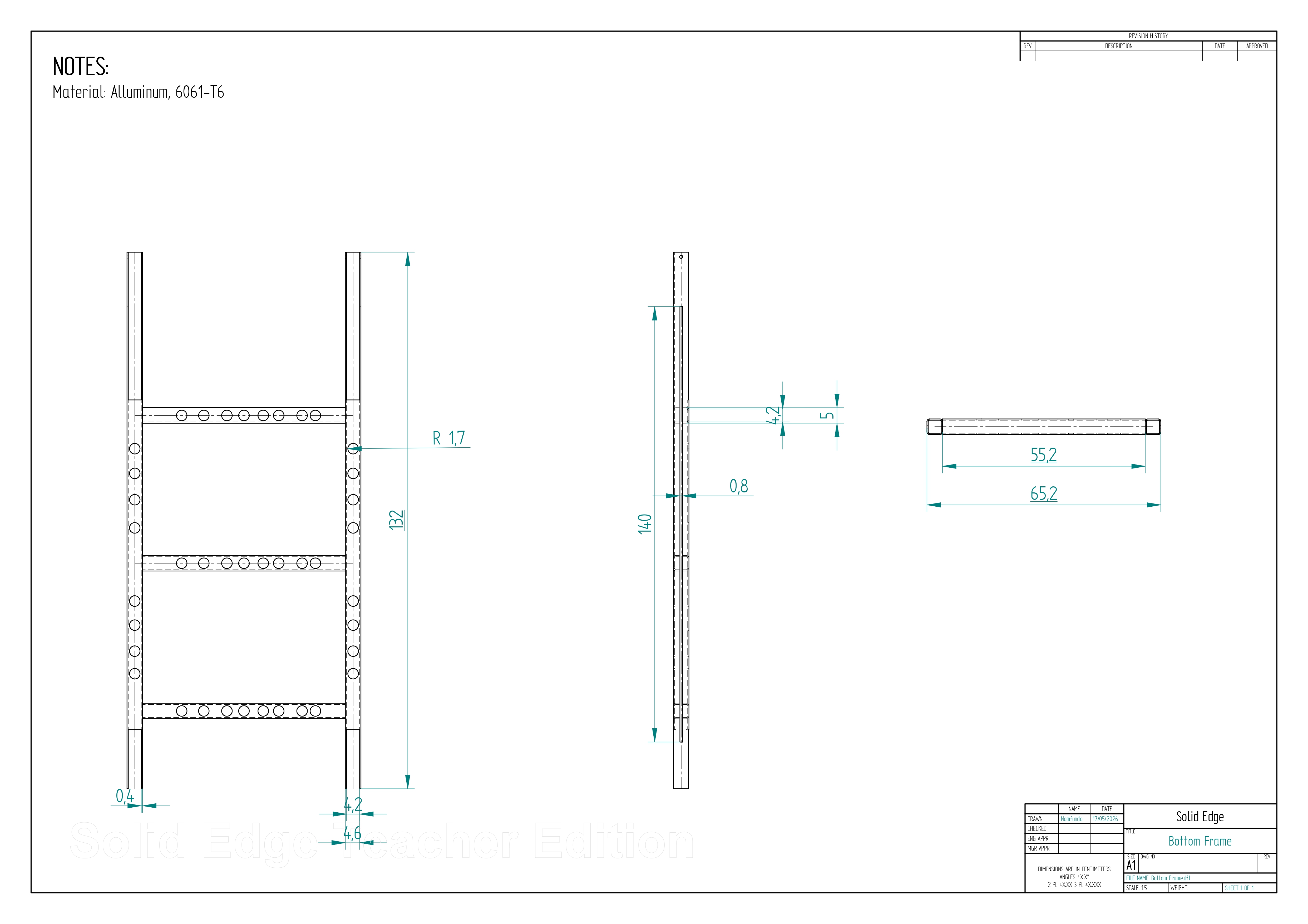
The engineering drawings document the final CAD model, component geometry, assembly details, and manufacturing information developed for the project.

Project Outcome
The final evacuation pod concept met the main design requirements by combining patient protection, structural strength, manual transportability, and environmental shielding into one integrated system. The design remained within the 40 kg pod mass target and was verified against the main structural load case using engineering calculations.
The full engineering report contains the detailed background research, user requirements, concept generation tables, manufacturing process planning, and full calculations. This portfolio page presents the main design outcome and key engineering decisions in a concise format.